This is a chronicle of my attempts to design and build a Do-It-Yourself (DIY) handcycle. A little background first.
I use a handcycle since my legs do not respond to my brain particularly well and vice versa. (My wife I am sure believes my brain does not respond to her – but I digress...) Riding a bike is not feasible. While I am relatively fast as compared to the handcyclist community (I won the U.S. Air Force Marathon, hand-crank division ), I have a difficult time keeping up with many legged cyclists But I enjoy riding with legged-cyclists since it allows me to push myself much harder as compared to riding solo. As well, I complained so thoroughly about my existing handcycle that I decided I had to design and build my own. Then I could complain to myself if nothing more!
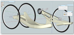
Before you are completely bored, here are design iterations :


Why is it difficult for a handcylist to maintain the same speed as legged cyclists? There are three main problems for a handcyclists as compared legged-cyclist:
- Power: To give you an idea of the difference between a legged cyclist and a handcyclist, a top-notch legged-cyclists will maintain 33 mph over a very flat 40K time-trial without many turns whereas the top handcyclist can only maintain 23 mph. If hills are introduced, the comparison for the handcyclists becomes decidedly bleaker since the arms cannot generate nearly the power required to lift the body as compared to legs. As an example, the next time you climb a ladder consider pulling yourself up with your arms rather than pushing with your legs. You will get the point immediately. No matter the amount of gearing involved, the arms will never match the legs. Now think of climbing 5500 feet with your arms over 100 miles of cycling…
- Turning: The handcyclist must slow considerably more on a turn as compared to a bike since the handcycle cannot be “leaned” into a turn due to the three-wheeled design. I roll my handcycle far more than I would roll a bike. The bicyclist need only lean more on an aggressive turn or as speed builds.
- Circulatory system: The human body’s design is one of the best in nature for long-distance hunting with the legs and picking berries with the arms/hands. Surprisingly, arm muscles are 38 percent less efficient as compared to the legs given the same muscle mass. Some of the best ultra-marathoners have put in over 300 miles without stopping. It would be completely impossible to have the arms carry one for such a distance without mechanical assistance. The aerobic use of the arms are hindered when compared to the legs.

For my design work (about five months) I used a free 3D program from Google called SketchUp. (http://sketchup.google.com/) The learning curve was a bit steeper than I expected. Additionally, SketchUp is not a true solids modeling program. But it is free! So I used it. Ultimately the design process lead me to a two-wheeled handcycle design. (I have yet to find a commercial handcyle with two wheels.) My design goals are to:
- Increase aerodynamic efficiency: A bicycle front wheel consumes about 7%-10% of the total energy. The problem with a 3-wheel handcycle is that all three wheels are essentially front wheels since none are protected as normal bicycle rear wheel is. One is out in front and the other two are out to the sides. And since the speed is lower on handcycling, the wheels may very well consume 30% of the power. With two wheels (and other aerodynamic efficiencies), I may decrease my aerodynamic drag and rolling resistance by enough to attain 11-13% higher speed. As an example, on a regular bike, the seat tube alone can decrease a rear wheel drag by 25%.
- Turning: Two wheels will allow me to lean during a turn and thus I can maintain more speed. But a handcycle’s three wheels allow for stability on stops and low speed. By moving to a two-wheel design, I would lose stability – especially on stops since I cannot just put my leg down to the ground. In order to regain stability, I have added two inline skate wheels as out-riggers. The wheel would contact the surface when the bike leans further than 12 degrees. For stops, I should be fine (hopefully!).
- Add disc brakes! I was coming down a very curvy mountain road in New York. Since I cannot lean into a turn, I was afraid that the considerable “G” forces would tip me over. The speedometer read 46 mph. At that point, I could smell my brake pads burning. My only choice was to put my shoulders/arms into the rear wheels to help generate some more friction and slow the bike until I hit a straightaway… or the bottom.

(Here a picture from that race and that hill -- -- Grand Mondo of New York)…
- Get rid of as many moving parts as possible! A handcycle seems to break down about 10 times more often than a bicycle. Bicycle design has been improved over many years and with many millions of users. Handcycle design is more primitive and without the size of community of users. My handcycle design deletes the “front” derailleur, requires only one chainring, uses a single “rear” cog, and uses a transmission hub with no rear derailleur. Additionally, the front fork and body both employ monocoque construction with carbon-fiber.
- Comfort: My existing handcycle is of the one-size-fits-all variety. Again, without a large community of users, there is not the financial rewards available for the manufacturer to maintain many sizes. For my design, I can have it fit me exactly.
IfIf one wants to really go fast on a bike, then I presume that the closer one gets to this design, the faster one will go -- downhill at least:

In order to build the handcycle, I decided to use carbon-fiber as the structural element. Carbon-fiber is stronger than aluminum, titanium or steel for a given weight. And it allows me to build the handcycle “in the garage.” Since the bike is one-of-a kind, I decided to use the “plug method” as compared to the mold method. With the plug method, one creates a foam plug (the shape) that is then wrapped in carbon-fiber and epoxy. Sometimes, the builder will then dissolve the foam with acetone after the carbon-fiber/epoxy cures.
Here are some of the pictures (and commentary) of the building process.
Start building… Build a base to hold the plug:
I printed the plan view of the base of the handcycle from SketchUp -- scaled to 1.06X on the length due to the 20 degree sloping angles of the base. The print was then adhered to malanite board (1/8” thick). The board was cut with a jigsaw to fit the plan view.
I also printed a side view to full scale as well. This was adhered to a ¾” thick MDF. This was cut and became a template for the base. Two of the MDF boards, connected with 2x4’s, became the base for the malanite board. The malanite was glued to the MDF boards/2x4’s. These became the working base for building the bike’s base (see picture below...)

After the glue dried between the malanite and MDF, I essentially had the form of the base with curves in the X, Y, and Z directions to match my design.
Base formed from urethane foam:
In the following steps I laid of sheet of ¼” last-a-foam 4305 on top of the above form. I applied a 1500 watt heat gun to the foam. The specs call for the form to be formable someplace between 230 and 260 degrees Fahrenheit. The foam fell into place by little more than gravity (use a gloved finger to add a little downward pressure) as foam reached the appropriate temperature. I then added the sides (2” x ¾”) foam. This took additional bending.


As the work progressed in bending the foam, gluing it and clamping it…

There are cracks in the urethane due to the turns against a 2” thickness:
But with enough filling and sanding, most can be made “right”
Here is the urethane base for the handcycle removed from the MDF/malimite base:


Inline Skate wheels housing:
Due to my fear that the base of the handcycle may not have enough depth in the edge to accommodate the vertical bending moments generated by my weight combined with the forces caused by bad bumps in the road, I wanted to beef up the sides. I decided to move the inline skate wheels into the base itself and to essentially increase the height of the sidewall of the base at the same time. This took a lot of time to cut the existing foam out of the base, build a foam mold of the wheel housing, and build that into the base foam.

Rough-out of Front Fork
The fork was roughed out in Styrofoam (2” insulation from Home Depot), layered/glued together to create a deep enough section. In order to cut the Styrofoam, I created a DIY foam cutter/hot-wire from NiChrome wire (from a local hobby store), a battery charger, and $5 worth of electrical conduit and eyebolts (again from Home Depot). I placed the hotwire through a router table in order that I have a movable guide for the straight cuts. The router table already had the guide. The hot wire worked very well – much better than I expected. I could cut through many inches of foam with ease. Matter of fact, the hot wire worked as well whether the foam was 3” thick or 8” thick. The moveable guide on the router table was invaluable.

DIY foam cutter (hot-wire):

There was not enough amperage with the batter-charger set to “slow charge.” As soon as I set the mode to “Start” (up to 50 amps), the NiChrome wire turned red and the contraption worked! I had no NiChrome wire breakage in all the cutting that I did – and it breezed through the cuts. I suspects that the amperage drawn was about right. No animals were harmed and no circuit breakers were tripped.
Roughed-out Front Fork:
The front fork plug is comprised of Dow Styrofoam (15 PSI compression rated). The urethane foam (used in the main base of the bike) cannot be shaped with a hot-wire whereas the Styrofoam can be. I decided to use the Styrofoam on the front fork due to large amount of shaping required and since I wanted to use the hot-wire to achieve that shape.

Testing the size of the foam plug:
After laying upon the base plug – built from the original design drawn in SketchUp – I found that the seat in particular required quite a bit of shaping to fit my body. Albeit, the original design was fairly close in overall dimensions, the design required a bit of tweaking in order to make the handcycle comfortable. After many hours (20?) of shaping with a sanding block and filling with urethane/Styrofoam/epoxy, I got to a point where I could probably sleep upon it now since it is so comfortable. Hopefully I don’t fall asleep on the road.

Base foam plug with rear dropouts, seat form and rough-in steering support:
The seat area and steering support was form out of Styrofoam with the use of the foam cutter. These were adhered to the base with gorilla glue.

Disk Brakes:
This is the rear dropout with rear disk brake (the equivalent of a front wheel on a bike). This took many hours of work. In this case I used a drill press, large stationary sander, and band saw to build the carbon-fiber dropouts out of ¼” flat carbon-fiber plate. I had designed the parts in Google’s Sketchup, printed it 1:1, adhered the printout to the carbon-fiber sheet, and cut the pieces out with a band saw. The lower dropout is comprised of a double thickness of carbon-fiber since the brake body required it for the bolts to secure it in place.

Front fork plug with crank and gear hub. The orange string is the chainline:

Front fork foam plug with gear hub (SRAM IMotion-9 speed…no derailleur required) and disc brake fitted;

Steering (Now the tough part…)
I actually had to build quite a few carbon fiber parts that comprise the steering. The headtube is 15 layers of carbon fiber – as are the steerer tube support tubes (2). Additionally, the flat ends (4) to the steerer tube supports required hand filing in order to accommodate the 1-1/8” steerer tube. My drill-press just could not cut the holes well enough through 15 layers of carbon fiber. It took 4 hours of filing to correctly size the holes. Also, it took a couple of tries in order to come up with an acceptable headtube. That is another story…
The “white” area around the carbon fiber is a material comprised of epoxy mixed with glass microballs. The microballs allow for sanding and leveling of the carbon fiber areas. Additionally, it is much lighter than 100% epoxy. This mixture of epoxy and microballs are applied after the carbon-fiber/epoxy was cured in place.
Now the steering head tube, steerer tube, and bearings are in place. The steering actually works.

I use a laser to align the pieces – base, front fork, head tube, and head tube supports. I therefore can feel assured that the pieces (base, steering, fork, wheels, dropouts) are in the correct position:

The orange string below is used to check the chainline to make sure the chain fits through the fork. Since this is using a hub transmission, the chainline stays put. There is only a single cog and a single chainring.

Foot Holders rough-out:
The foot holders are roughed out from Styrofoam with the use of the DIY foam cutter. I then used foam sanding blocks to finish the shaping.

Vacuum Bagging:
The better method of impregnating and finishing the carbon-fiber is to “vacuum-bag” – put the carbon-fiber and epoxy, during the curing process, under pressure via a vacuum bag technique. In order to have a better vacuum bagging process, I built a DIY vacuum controller (about 5 hours or work including numerous trips to Home Depot). The reservoirs are constructed of schedule 40 (pressure type!!!) pipe and caps with holes threaded to take ¼ NPT fittings. Here it is:

Testing a Venturi-based Vacuum Bagging System:
The system did not work the first time since I had a one-way valve in backwards! After diagnosing and fixing the problem, it worked! Matter of fact, when the valve to the vacuum bag is turned off, the system held vacuum for over 24 hours without losing an inch.

Foot-holder wrapped in carbon-fiber:
I found that wrapping the foot-holder was more difficult than I expected. It took many tries. I used 3M spray adhesive to hold the carbon-fiber in place as I wrapped the foam. This helped considerably. Many DIYers use the 3M 77 product.

Testing the plug:
I am glad I performed this test since on the first attempt, I could not insert the front wheel into the dropouts due to the front fork (the foam needed additional shaping). Additionally, I have used a fair amount of epoxy mixed with abundant amount of glass microballs (very light weight material that is quite sandable mixed into the epoxy) to finish, feather and add support to the foam plug.

View from the rear:

Building the Handles for the Crank:


Layout the Carbon Fiber on Plug:
I have found that the best way to cut the many, many pieces of carbon fiber is to follow a process. That process is,
· Build paper template in order to have the carbon fiber fit properly.
· Spray light adhesive on back of template
· Adhere paper template to the CF. This will help alleviate the fraying that occurs easily with a “Twill” carbon fiber that I am using predominantly.
· Cut carbon fiber AND accompanying peel ply (if peel ply is to be used) to the template.
· Peel off the template after the carbon fiber is in place on the plug.

Foot Holder after Vacuum W/ 3 Layers of CF:
The sanded carbon fiber foot-holder has the plug’s Styrofoam melted out with acetone. The foam had “crushed” some at 19” of vacuum. Therefore, the finish is not perfect. This may take 4 or 5 coats of resin – with the appropriate sanding between layers – in order to get a better finish. If the foam had not crushed, I think the finish would have been better.

Wow, this is so cool!!!
ReplyDeleteOne correction though. I am a 2 wheeled cyclist, and I had a tough time keeping up with you!
Thanks... maybe downhill I can beat you..but any 80 year old woman non-rider can beat me uphill... You guys sure make me work hard trying to keep up.
ReplyDeletePretty f'ing amazing, Bruce. But you didn't say what type of beer was in the cooler... I like the dissolving foam plug idea. Sounds like the "lost wax" process used in casting metal.
ReplyDeleteNo matter the type of beer -- usually cheap -- there is not enough. The carbon fiber layup requires even more of it as compared to shaping the foam... Maybe one every 10 minutes
Deletenice post man, you always come up with really interesting and informative post.
ReplyDeleteDodge Steering Stabilizer
bro thanks for the tip on the science project i have for school
ReplyDeleteThis blog post provides an interesting and detailed look into the challenges of handcycling.
ReplyDelete