The
winter is here and I needed a winter project. This is especially true since I
overworked tendons in both elbows with the training over the last year and thus require a rest. I
had established a goal to set the course record for the Air Force Marathon in
September (I did accomplish that). But the heavy training -- 200 to
300 miles per week -- starting last March took a toll. The tendons were getting increasingly
sore as the training continued, but I felt that if I took extensive time off from training, I could not
meet that goal. Now I am taking the time off to heal (and
it is a VERY slow process) and filling the time with the design and building of
another 2-wheeled handcycle.
My
design objectives have not changed much from my original handcycle design:
- Build a handcycle that can be balanced. My first handcycle design had a trail that
fell well out of the normal range for today’s 2-wheeled bikes. That was due to the very low angle of the
front wheel’s headtube. This bike has a Trail that is about 60mm and an headtube angle that is consistent with many of today's bikes.
- Keep the base/sitting area low enough to the ground that I can use
my hands to balance the bike at stops.
- 2-wheeled. If each wheel of
a 3-wheeled handcycle is essentially equivalent to a “front” wheel of a regular
bike (no protection), and if a bicycle’s front wheel requires 40 watts of power
at 20mph (whereas a protected rear wheel may only require 5-15 watts), then the
handcyclist must overcome a real
disadvantage compared to a 2-wheeled bike. Rough math would predict that the
3-wheeled handcyclist must generate about 65 or more watts for wheel rotation
at 20mph as compared to a 2-wheeler. That is a lot.
- I have to lie down and cannot use a kneeler-type handcyle. So the design reflects this.
- Paint it. I am not going
through the extra work for beautifying the carbon-fiber. Of course, I can smooth out the carbon fiber
with light weight body filler and then either paint it or put on one more layer
of large pieces of carbon fiber. But I will probably opt for the paint.
 |
| Newest desgin |
·
Sweet-looking. Hey, if I
get to design it and build it, I may as well build something for which I like
the looks! Of course beauty is in the eye of the beholder. One only a parent could love...
- Transmission hub (I-Motion9) for gearing. This somewhat simplifies the design and potentially gets rid chainline problems.
This
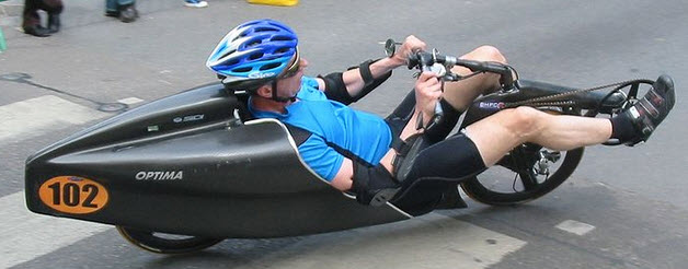
design (above) is therefore quite different from the first handcyle (below).
 |
| First Handcycle design I built...sans wheelcovers... |
The leg-holders will be added after I position/fit myself to the bike. The dummy in the design is fairly accurate to my size -- but by no means perfect. ...maybe better looking though.
As
you can see, the front wheel is a small one in order to accommodate the much-more-normal headtube angle. Again, this
headtube angle is much closer to that of a road bike as compared to my previous design/attempt. A large 650 or 700 wheel would cause the steering and crank to completely obliterate my line-of-sight unless I lift the base. By lifting the base, I would no longer have easy reach of the ground. Therefore, the small wheel...
The front wheel is a 451 (20” x 1.125”) and home-built since I am putting in a transmission hub. The hub has 36 spoke holes.
A
number of features have percolated from this design. One is that my feet will be
closer together and therefore -- hopefully -- I will be a bit more streamlined. The small wheels of this design keeps the wheelbase shorter and therefore the weight of the frame lower.
Another design consideration -- Since
I am maintaining front-wheel drive (rear wheel drive is a whole other topic) on the bike, I have a
chainline that must be redirected on the return side in order to allow for the chain
to go through the fork in a placement that still allows for the integrity of the
fork.
For the transition from design/paper to a foam plug, I built a foam hot-wire cutter that can cut through a large block of foam (very large!). The foam cutter is essentially built from a three-legged shelf for which the fourth leg is the hot wire.
The battery charger was from my last (and much smaller!) foam cutter design.
With this design, I attached a spring to the end of the nichrome wire. This worked much better than I expected. The nichrome wire never broke in all the cuts. Additionally, I used a router to sink a movable square into the table top in order to insure straight cuts.
To assist in cutting the foam according to design, I attached a paper outline (printed 1:1) of the base (or fork) to 2 sides of a large block of foam. The foam was built up from 2" thick foam board -- the pink stuff from Home Depot. I employed 3M's 77 adhesive for holding the foam together. The adhesive works quite well -- but be liberal with it. The benefit of a spray adhesive is that during sanding through the adhesive, there is no problem.
The
cutter worked very well in building the rough shape of the base and fork. I then used a drywall sanding screen to add rounded edges. Within a day, I had the foam plugs of the base and front fork pretty well completed. When cutting
the foam, I made a number of changes to the design as you can see below:
 |
| View from the rear of the bike |
 |
| Fitting the foam together |
 |
| Testing the headrest/base for fit |
When
building the foam plug, I decided to keep the whole base deeper than the design drawings. Originally, the design drawings had a center tube. I will use the additional
depth/space for hydration bags when I remove the foam with acetone.
I attempted to concoct a filler for the dings and such of the foam plug. Others have used the foam crumbs from sanding in combination with white glue as a filler. If you do this, you must water down the glue substantially since the glue is not very sandable otherwise.
 |
| Homemade foam filler -- Add water to glue! |
From
lessons learned, I covered as much of the foam plug with a layer of carbon fiber
rather quickly. The last handcycle's foam plug I built got dented and even broken after falling
on it). Addding the carbon fiber helped in stabilizing the
foam.
 |
| Wood form to hold handcylcle square and plumb |
In
order to align the foam plug -- before any carbon fiber is added -- I built a wood base/holder with 135mm front fork offset and 100mm offset for the rear wheel in the base. The wood base is absolutely mandatory in order to square and plumb the plug. If I did not construct this, I could be assured of having a bike that would not track properly. Even with this wood base, I used a "laser" level that shot a light the length and height of the holder.
Into the foam, I mounted front
and rear dropouts cut from carbon fiber plate.
Two of the dropouts contained the disc brake holders. With the dropouts in place, and with the wood
base built for holding the plug square and plumb, I then applied a carbon fiber
layer to much of the foam and drop outs to hold everything in place.
 |
| Adding dropouts into foam plug |
 |
| Drawing Displaying Disc-Brake Bracket |
This picture below displays the bottom bracket (with crank) as well as the idler in place. The idler is taken from an old derailleur's return cage. The idler changes the chain’s return direction.
 |
| Bottom bracket |
The next phase of work required that the headsets/steerer tube be built into the
frame and fork. I used AHeadset ZS (Zero Stack series) for
a 2” headtube and 1.125” steerer tube. The total height of the headset
configuration took more space than I initially estimated. Therefore the design changed slightly in the
front fork to accommodate the height.
The change in height of the foam ply was fairly easy to achieve by
merely gluing on more foam and shaping it.

In order to ensure that the headset would align properly, I install the headset parts in carbon fiber tube. Each carbon fiber tube was sized to the component first (lower fork, base, upper fork). Then the tube for the base case epoxied in with ar carbon fiber layer to the base. After that cured, I epoxied in the fork's upper and lower headset tubes -- with the steerer tube installed through all headsets. I used the laser level to plumb and level each part and the bike. I then applied a layer of carbon fiber throughout the headset to hold all parts accurately in place. After that cured and after a thorough check to ensure that the parts were properly positioned, I added many layers of carbon fiber.
With
the headsets in place, I was then able to check out the chainline, disc brakes
and steering:
 |
| Well, maybe not beautiful... |
The
disc brakes and headsets aligned very well – phewwww.
During the downtime as the fork's epoxy is curing, I add light-weight body filler to the base. I think I sand away 98% of what I apply... and then I do it again and again. I guess when I paint it, I will learn whether I performed a good finish job.
 |
| Lightweight body filler for smoothing out carbon fiber |
The
front fork requires quite of bit of work in order build out the thickness of
the fork where it carries the majority of the stresses. This will be the basis of a later update.
 |
| Front fork before the buildup of carbon fiber |