Sunday, September 7, 2014

Handcycle -- New Base with Improved Aerodynamic Design

Small changes in shape can have a big impact on aerodynamic drag.  Surprisingly so.

Cd of 0.18
The 3D design:


I am testing a new base to my handcycle for which the design has been put through hundreds of iterations of Computation Fluid Dynamic (CFD). That is, I take the 3D design, put it into a virtual "software" wind tunnel, see the results, make changes to the 3D design, and do it again -- hundreds of times. As small changes improve the aerodynamics, I maintain those changes in the 3D design.  My challenge is to reduce the aerodynamic drag on the handcycle.

The base is connected to my existing front fork (the front fork takes much longer to build).


Some of the rules of thumbs of design that I thought would hold true, did not.  For instance, a "longer tail" did not give the best results.  A "narrower wheelbase" did not give the best results.  "Closer to road" did not give the best results.  That is not to say that the rules of thumbs are wrong -- but only that the best overall design results may be achieved with otherwise.

That being said, the best measure of aerodynamic design is of course, "How fast is the handcycle on the road?"  This handcycle is easily the fastest I have ridden.  

PR's:

In the first three days of taking the new bike out on the various rides (that I have done many, many times) I broke three of my course records easily.  The first ride was a 25 mile "time-trial" with something like 14 stop signs and a 450 foot elevation gain. I averaged 18.4 mph.  The next ride was a 42 miler for which there is about 500 foot gain and too many stop signs to count.  I averaged 17.1 mph,  The third ride was a 72 miler with a 800 foot ascent with 30+ stops including numerous stoplights.  I averaged 17.4 mph. None of the rides were "all out" -- but they were definitely above a leisurely pace (for which I know little about).

Of course I do not stop completely at all stops -- but I have to slow to a a max of 5 mph since the corn, soybeans and grass is high -- and I am low to the ground.  Most stop-sign corners are not mowed -- so I have to slow considerably.  And I do literally stop at stop lights. Of course then I have to speed back up -- the hell of handcycling.  On the flats, without wind, I am guessing that I average in the high 19's -- maybe even into the 20;s.  But there is nothing really flat -- even 20 or 30 feet ascent over a mile makes quite a difference.

Why faster:

So why is the bike faster?  Through the many iterations of CFD on the 3D design, I found that the small changes added up quickly to a better overall drag coefficient.  Most importantly, I was able to: 
  • Reduce the trailing drag by reducing the compression of air under the handcycle;
  • Replace the rear axle with a "wing" shape;
  • Contour the headrest/hydration bag area (many! iterations);
  • Keep rear wheels vertical.  A 5-10% slant of the rear wheels increased drag.
  • Reduce frontal area under the legs.  The base comes to nearly a point at its front edge.
  • Much lighter.  The base lost 15 lbs!

Flex:

The above times were completed with a fair amount of flex in the base.  I added four more layers of  carbon fiber (two on the top, two on the bottom).  This helped -- but the bike still had too much flex when  I was climbing hills.  So I added a 2-part urethane foam to the interior of the base as a structural element. The urethane can withstand 20 lbs./sq. in.  At all out, I might be producing 200 ft-lbs/sec. Given the huge surface area of the base, the urethane foam appeared to be more than adequate. The urethane (2 lbs. per cu.ft.)  greatly reduced the flex -- and was a simple, simple solution to the problem,  The addition of the urethane only added a quarter pound to the base and required about an half-hour of work -- mix the 2-part liquids, pour it into the base, and in 5 minutes, it expands about 20-25 times the liquids volume. In fours hours, the urethane is hard.

Added features:

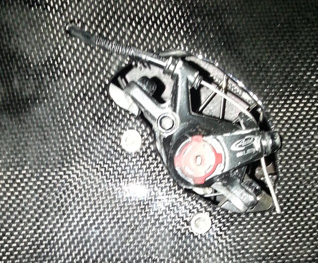
2 rear disc brakes!!!  Man, this bike can slow or stop much quicker.  Thus I can come into a turn (or stop sign) at higher speed and reduce the speed quickly.


Large hydration bag.  I now have a 6 liter hydration bag instead of two smaller ones. 

Positionable hydration line holder. I can place the holder out of the way for when I enter or exit the bike.Plus the water line is always available by moving my head forward on inch.


Regular wheels (thus cheaper!!!). These wheels cost a total of $290 with the Shimano hubs.  I used a 1/2" x 20 tpi hex-head SS bolt going into an aircraft-aluminum axle holder wrapped in about 30 layers of carbon fiber fitted into the "wing" axle.


I have hit some big-ass holes, ridden over miles and miles of newly "tar and chipped" roads (for which my teeth nearly vibrated out of my jaw).  The axles appear to be quite strong.  My axle holders are but 1/2"x 20 tpi automobile aluminum wheel hub nuts -- 2" long, costing about $4 apiece.

This may be my last base I build since it might be very difficult to improve upon it...

USB Rear Light:

The base holds a large lithium-ion polymer battery that can hold a week or two of charge for the 15-LED rear light.  There is a USB line hanging out of the rear (see pictures above) to allow for EASY charging!

Monday, May 12, 2014

Add two DIY Carbon Disc Wheels

Finished Wheels with Carbon Fiber Covering

If you have read this blog previously, you probably get a sense that I hate to spend good money on expensive frames and parts if I can figure out a way to build those myself for a much more reasonable price. The one area for which I may be able to gain the greatest benefit (speed) for the least amount of cash, is to build disc wheels.

My initial search of what others have done relative to DIY disc wheels was to find that many had bought sheets of plastic, cut a circle from it, slice the circle from its center to its perimeter, and make a "cone" or disc that fits from the hub, to the spokes and to the rim.  Then the do-it-yourselfer would then glue, tape, and/or mechanically fasten the plastic disc in place relative to the hub, spokes and rim.

Some studies even propose that DIY disc wheel covers perform equal to the expensive carbon fiber disc wheels.

As I was searching the subject, I found that many disc wheels actually contain spokes.  Well my existing wheels contain spokes.  And those wheels do not have rim brakes...

After ordering 24"x24" - 3/32" ABS plastic sheets, I retrieved the delivered box from the front door, only to find that the box of plastic was actually pretty heavy.  I do not need more weight for the handcycle! So I decided to use a a similar technique as mentioned above, but with a single layer of carbon-fiber substituted for the ABS plastic.  This would reduce the weight considerably.

The process of building the wheels was to use one layer of carbon fiber for each disc (one disc per side of each wheel).  I laid out the carbon fiber fabric on the ABS plastic I had bought (with the intention of building wheel covers). This ABS plastic was cut to a diameter that slightly larger than the wheel rim. I then applied the West System 206 epoxy to the carbon fiber fabric. The side of the carbon fiber fabric on the ABS-side was to be the finished surface.  After the epoxy cured, I was able to remove the carbon fiber from the ABS plastic.  It did not stick (to speak of). This gave me a fairly clean, flat and finished piece of single-layer carbon fiber.


Each  carbon fiber disc, after I sliced it from the center out and cut the hole for the hub, was glued to the rim. Of course the hub and spokes were in place on the rim.  The discs were oversized initially  There is an overlap now where the disc was sliced from its center outward as it is fitted to the hub outward to the rim. This is to accommodate the dishing of the wheel.  I applied epoxy to the overlapped area of the disc.


After the epoxy attaching the carbon fiber disc to the rim cured, the extra carbon fiber that extended past the edge of the rim was removed with a dremel tool.  

The first 30 miles on the DIY Carbon Fiber Wheel Covers went quite well.  I was surprised that the wheels were not "louder."  In the past, I have often heard cyclists with carbon-fiber wheels approaching me long before I was passed due to the vibrations/drum effect.  I expected the same from these.  But my expectations were not quite met.


Thursday, May 1, 2014

After 150 miles...

Delta-handcycle after the first 150 miles
My thoughts after 150 miles...

1 -- The handcycle feels pretty good.  That is, it fits like a glove -- or more precisely -- a recliner fit to my body.  As an example, when the weather is bad or I start a late workout I put the handcycle on the rollers, indoor, and throw a couple of  movies on the "big screen", I often do not get off the bike even after I finish the workout. Instead, I continue to lay on the bike to finish the films.  Hell, it's more comfortable than a chair.

My recliner for movies...


2 -- The disc brake is fantastic.  I will never ride a handcycle without a disc brake again.  On my next bike, I will design two of them into it.
!

3 -- The bike is LOW to the ground.  That makes it nice for getting off the bike.  I just slide over to the garage floor.

 4 -- Faster? I don't yet know if the bike is faster as compared to my Force-G or not.  My right shoulder is 4-5 months past the surgery.  The shoulder is getting stronger quickly but I cannot push particularly hard.  Though on a couple of small downhill areas of my "nightly" ride, I would hit 26 mph max (after a climb). In comparison, without pushing, I did hit 27 mph with this bike.  So, this bike is at least as fast as my old one.  BTW, I had modified the Force-G such that I was laying pretty flat on it as well.  I am carrying about 7 extra pounds on the bike (about equally divided between the transmission and the carbon fiber). As well, after many months of little activity I have gained 7 pounds of fat.

5 -- I had to rebuild the handles in order that my hands would be more comfortable (the other handles were too small). Additionally, I wanted the right handle to have the twist shifter built right into it.  The design works out very well!  It is comfortable for short rides.  The real test will come on the 200K and longer rides.  That is when the hands cramp and shifting becomes more difficult.

Right-side handle with twist shifter built in


Wednesday, March 5, 2014

Delta Handcyle on Rollers

The shoulder is healing.  At this point, I am allowed to ride 8 minutes a day at about the lowest pressure. It's a bit hard to suck up to the fact that it hurts more to do 8 minutes of riding on rollers than to do a 12 hour cycling event.  But then again, it better to be doing 8 minutes than nothing!  I finally have my newest DIY handcycle on an old set (25 year old!) of rollers that have been accumulating dust for far too much time.  The bearing are good, and the rollers spin like a charm.  And they are very quiet.

Over the last weeks, I have been working on a self-righting mechanism for the steering.  I have tried very heavy rubber tie-downs (not bad), stainless steel spring (not bad), and a carbon-fiber composite spring (needs some work).  I may use two stainless steel torsion springs -- one on each end of the steerer tube to self-center the steering/fork.

If the weather is warm this upcoming weekend, I will be using some acetone to dissolve the foam inside the rear horizontal cavity.  It is there that the two 100 oz. hydration bags will be placed.  The holes are drilled in the carbon-fiber to fit the mouth of the bags (see picture below).  Otherwise, the bike is ready for the road!


Sunday, February 9, 2014

Delta Handcycle Version in Carbon Fiber


Delta Handcycle Version in Carbon Fiber


The delta (two rear wheels and one front wheel) design is nearly finished.  I still have to add finish epoxy coatings to the bottom and put a UV protective clear coating over the full handcycle.  As well, I have to add the cables for the brake and shifters and the shifter itself.  


The rear wheels spin well within the wheel housings.  Each rear wheel tilts in about 5 degrees from bottom to top.  You might notice the large structural "keel" (unfinished) running the length of the base.  

The chain incorporates half link(s) in order to size the length correctly for the transmission.  Again, I am using a transmission system in order to remove some problems that I often encounter with shifting. In particular, if I have to stop suddenly and am in a high gear without down-shifting, I put tremendous pressure on my shoulders trying to get the bike moving again.  On my aluminum handcyle, I broke two welds over the last couple of years when caught in such situations.  With the transmission, I can shift when stopped.  


I am not sure when I can put this on the road since  I am still in the process of getting my strength back from rotator cuff surgery on the right shoulder.  A full tear and a partial tear has slowed me down a bit.  Luckily I am at the point of adding very light strengthening exercises in my rehab process. 


Sunday, November 17, 2013

Computational Fluid Dynamics (CFD) and Handcycle Design

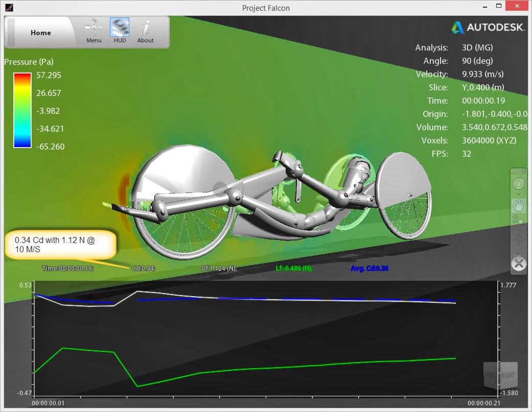
A wind tunnel, I do not own.  So I have been waiting for the day that a Computational Fluid Dynamics (CFD) program would be available at little cost. The idea of a computer application taking the place of a wind tunnel makes sense -- especially for a hobbyist like myself.  AutoDesk Labs is testing a CFD program -- Project Falcon -- and I grabbed a free copy of it as soon as I read about it.  I was able to take my 3D Sketchup model to an STL file and Project Falcon is able to import the STL file. (An STL file is usually used for 3D printing.)  From this, after tweaking a few setting in Project Falcon, Project Falcon was able to calculate the Cd (Coefficient of Drag) of my 3D Sketchup models.  

The lower the Cd the better! The Cd correlates to the wind resistance of the handcycle. The frontal area is multiplied by the Cd.  From the Cd, frontal area, and wind speed, one can determine the Newtons of force and from that the watts required at a set speed in order to overcome air resistance.

F= CdA p [v^2/2]
where:
F = Aerodynamic drag force in Newtons.
p = Air density in kg/m3 (typically 1.225kg in the "standard atmosphere" at sea level)
v = Velocity (metres/second). Let's say 9.33 which is 20.8mph


Since I am hoping for a faster handcycle and since I am getting older but not stronger, my intention is to build a design that significantly reduces drag and thus allows me to move at a higher speed given the same amount of power. Without this software, my option is to design a handcycle, take it out on the road, and see if it is indeed faster.  With Project Falcon, I can tweak a design and check to see if it is indeed has a lower Cd and therefore faster.  

The two-wheel design has a much better (therefore less) drag as compared to the 3-wheel design.  Given my current injuries -- I need stability that the 3-wheel design gives for the next cycling season.  Here is the 3-wheel Delta design that I am hoping reduces air resistance:


An important concept in this design is the shape of the base that migrates into the plane between the rear wheels.BTW, the front fork is from the first bike I designed and built.  

Here is the result of Project Falcon's calculation on my 2-wheeled handcycle design.  The Cd is a mere 0.16:


And here is Project Falcon's CFD result with my newest 3-wheeled handcycle design.  As you can see, the Cd is nearly doubled that of the 2-wheeler.  Of course, the design still has a Cd is that is much less than a racing bicycle (0.88 -- see below).  But my arms are much smaller than most legs -- so I can use any improvement


Here are two pictures from the "smoke" version of Project Falcon's wind tunnel imitation.  One is the representation of a plane that cuts through the shoulder.  The second picture represents a plane through the center of the bike.  As you can see, the design of the rear of the bike around the shoulders, appears pretty good.  The center-plane of the bike gives off a fair amount of turbulence though:


I may increase the size of the headrest behind the helmet in order to see if that improves the Cd.


From the above formula, in order to go about 20 miles per hour with this handcycle (assuming that Project Falcon is correct!), I would need to produce about 45 watts in order to overcome the air resistance.

The frontal area is somewhere around 0.28 square meters:


Cd= 0.32
Area = 0.28 meters square
AirSpeed = 9.33 meter/seconds
AirDensity = 1.225kg/m3

F= CdA p [v^2/2]
F = (0.32 * 0.28) * 1.225 * (9.33 * 9.33) / 2
F = 4.77

Watts required to overcome air resistance = F * AirSpeed
= 4.77 * 9.33
= 45 watts

But all of this makes many assumptions...


Here is an copy of a page showing the Cd's of various forms of cycling:


Monday, September 16, 2013

Newest Handcycle Design

Newest  Handcycle Design... Is it ugly or beauty?


Could you take this home to your mother or would your father have to pull you off to the side and discuss your sanity?


As you can see, during the building process, the design changed a little bit in that I decided to have larger wheel fairing for a better aerodynamic shape. The wheel fairing also take care of a literal problem: getting road debris in my eyes.  After one ride on my old handcyle, I had to have an opthamologist remove a splinter embedded in my eye.    As well, I lowered the bike another inch or so in comparison to the original design.

The bike is very comfortable -- especially the leg holders.  I may fall asleep on it on long rides...


One of the better improvements that this handcycle has over the previous version is that there is a center bean that runs from (and including) the neck of the base to nearly the end of the seating area/shoulder area.  The beam divides the interior of below-the-seat area.  With the strong center beam the bike flexes far less than its predecessor.  The center beam is very strong and is composed of a number of layers of biaxial carbon fiber sleeve While this is more expensive as compared to carbon fiber fabric, I am really impressed with the ease of use, integrity and strength.  The steering appendage is composed of the same material.

The front fork area that takes a lot of stress is composed of about 32 layers of carbon fiber.  For further strength in the fork, the leg holders add a lot of structural support.  The underside of the leg holders actually curve into the fork (although it is difficult to see from the front).  

As you can see, there is little frontal area for this design.


During the process of building the last handcycle, I was not at all happy with the front fork's building process.  For this one, I decided to build the structural part of the neck-to-fork connection first, insert it into the fork's foam plug, and tie the fork and structure together.  This ensured that the neck-to-fork connection would have very close tolerances on fit.  This process gave me immeasurably more confidence in the fork.

Handcycle -- Front fork plug and headset


The retractable training wheels are needed.  I tried to use my hands-on-the-ground to stabilize the handcycle at a stop, but I just could not balance at the start-up of the bike from a dead stop.  After I learn to ride again (that is, balance the handcycle), I hope to add an arduino/motor to raise and lower the stabilizing wheels at, let's say, 6 miles per hour.  Of course I am assuming that I ultimately can balance the bike at a higher speed.  During my second ride (the ride after adding the retractable stabilizing wheels) I did balance the bike for short periods -- but I also broke a weld joint on  retractable wheels assembly.  I stupidly used some quick epoxy which was only about 3K PSI in tensile strength.  The West Systems epoxy has double the strength.  Ultimately I will probably have to reinforce the mechanism for which the retractable wheels rotate back and up.


The chainline is slightly different in the built version as compared to the design. In the end, I decided to have two idlers -- one a power-side idler with a cog (toward the rear of the fork) and one a non-power idler (to the front of the fork).  Thus, I have but one chain.  The original design called for two chains.  From what I read, a single chain with two idlers is more efficient than two chains with an intervening cog set.  So far, it appears to be a good decision. I may add a chain guard on the leg holder later but with my bow-leggedness, it is not a problem at this time. Maybe over 100 mile ride I will feel differently.


I continue to use the I-Motion 9 speed transmission (which adds a number of pounds to the bike) but I feel quite certain I could change this to a 9 or 10 speed derailleur if I need different gearing.  The nice thing about the I-Motion is its very evenly-spaced gearing. One of the most important features is that II can change gears at a dead stop.  Since I cannot stand out of a dead stop, I need to make sure I am in a low gear at fast intersections!

The above chainring is 54 teeth.  
The disc brakes are 180mm rotors with the well-known, tried and true, BB7 mechanism.
The front wheel is a 24" while the rear wheel is a 700cc.  I built them -- so if they fail, it is indeed my fault!

The bottom bracket is 68mm and is about as low as I can get it while maintaining a very slight clearance for my hands/grips/"pedals" relative to my legs.

The interior foam that formed the plug (to which I added the carbon fiber) is dissolved out with the liberal use of acetone.  Matter of fact, I have a bit of the remnants of the foam dotting my driveway.  

One aspect of the design improvements on this handcycle is that I can remove the fork from and attach it to the base in a matter of seconds (other than the cables).  This can occur because I did a much better job of designing the fork/neck connection structurally and with bearing sets that allow for excellent alignment.  The fork's steerer tube is 1" with a permanent top cap of carbon fiber attached to the steerer tube.  The top cap allows the steerer tube to be pulled out with ease and for a separation of the fork from the body.  

My hydration bags (I usually like to carry 200 oz. of  fluids on 100 mile and above rides) will fit into the internal seat area.  

The leg holders are very sturdy.  There may well be eight or ten layers of carbon fiber in them (I lost track). I fell twice at low speeds (before adding the training wheels) for which the leg holders took the brunt of the impact. I literally could not tell where I hit.  My intention was to have the leg holders provide protection -- and they appear to work.   

The leg holders provide a stop for excessive turns of the fork.  That is, a leg holder will terminate a turn by hitting the base.   Over time I may have to shave down the back end of the holders in order to increase the turning angle.  Time will tell.

Below is an early view of the handcycle during the building process. Let's call it a comparison of aerodynamic shapes...  I like them both! I wish I didn't have to hang all the hardware onto the handcycle though.