Monday, September 16, 2013

Newest Handcycle Design

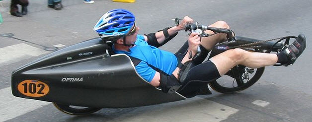
Newest  Handcycle Design... Is it ugly or beauty?


Could you take this home to your mother or would your father have to pull you off to the side and discuss your sanity?


As you can see, during the building process, the design changed a little bit in that I decided to have larger wheel fairing for a better aerodynamic shape. The wheel fairing also take care of a literal problem: getting road debris in my eyes.  After one ride on my old handcyle, I had to have an opthamologist remove a splinter embedded in my eye.    As well, I lowered the bike another inch or so in comparison to the original design.

The bike is very comfortable -- especially the leg holders.  I may fall asleep on it on long rides...


One of the better improvements that this handcycle has over the previous version is that there is a center bean that runs from (and including) the neck of the base to nearly the end of the seating area/shoulder area.  The beam divides the interior of below-the-seat area.  With the strong center beam the bike flexes far less than its predecessor.  The center beam is very strong and is composed of a number of layers of biaxial carbon fiber sleeve While this is more expensive as compared to carbon fiber fabric, I am really impressed with the ease of use, integrity and strength.  The steering appendage is composed of the same material.

The front fork area that takes a lot of stress is composed of about 32 layers of carbon fiber.  For further strength in the fork, the leg holders add a lot of structural support.  The underside of the leg holders actually curve into the fork (although it is difficult to see from the front).  

As you can see, there is little frontal area for this design.


During the process of building the last handcycle, I was not at all happy with the front fork's building process.  For this one, I decided to build the structural part of the neck-to-fork connection first, insert it into the fork's foam plug, and tie the fork and structure together.  This ensured that the neck-to-fork connection would have very close tolerances on fit.  This process gave me immeasurably more confidence in the fork.

Handcycle -- Front fork plug and headset


The retractable training wheels are needed.  I tried to use my hands-on-the-ground to stabilize the handcycle at a stop, but I just could not balance at the start-up of the bike from a dead stop.  After I learn to ride again (that is, balance the handcycle), I hope to add an arduino/motor to raise and lower the stabilizing wheels at, let's say, 6 miles per hour.  Of course I am assuming that I ultimately can balance the bike at a higher speed.  During my second ride (the ride after adding the retractable stabilizing wheels) I did balance the bike for short periods -- but I also broke a weld joint on  retractable wheels assembly.  I stupidly used some quick epoxy which was only about 3K PSI in tensile strength.  The West Systems epoxy has double the strength.  Ultimately I will probably have to reinforce the mechanism for which the retractable wheels rotate back and up.


The chainline is slightly different in the built version as compared to the design. In the end, I decided to have two idlers -- one a power-side idler with a cog (toward the rear of the fork) and one a non-power idler (to the front of the fork).  Thus, I have but one chain.  The original design called for two chains.  From what I read, a single chain with two idlers is more efficient than two chains with an intervening cog set.  So far, it appears to be a good decision. I may add a chain guard on the leg holder later but with my bow-leggedness, it is not a problem at this time. Maybe over 100 mile ride I will feel differently.


I continue to use the I-Motion 9 speed transmission (which adds a number of pounds to the bike) but I feel quite certain I could change this to a 9 or 10 speed derailleur if I need different gearing.  The nice thing about the I-Motion is its very evenly-spaced gearing. One of the most important features is that II can change gears at a dead stop.  Since I cannot stand out of a dead stop, I need to make sure I am in a low gear at fast intersections!

The above chainring is 54 teeth.  
The disc brakes are 180mm rotors with the well-known, tried and true, BB7 mechanism.
The front wheel is a 24" while the rear wheel is a 700cc.  I built them -- so if they fail, it is indeed my fault!

The bottom bracket is 68mm and is about as low as I can get it while maintaining a very slight clearance for my hands/grips/"pedals" relative to my legs.

The interior foam that formed the plug (to which I added the carbon fiber) is dissolved out with the liberal use of acetone.  Matter of fact, I have a bit of the remnants of the foam dotting my driveway.  

One aspect of the design improvements on this handcycle is that I can remove the fork from and attach it to the base in a matter of seconds (other than the cables).  This can occur because I did a much better job of designing the fork/neck connection structurally and with bearing sets that allow for excellent alignment.  The fork's steerer tube is 1" with a permanent top cap of carbon fiber attached to the steerer tube.  The top cap allows the steerer tube to be pulled out with ease and for a separation of the fork from the body.  

My hydration bags (I usually like to carry 200 oz. of  fluids on 100 mile and above rides) will fit into the internal seat area.  

The leg holders are very sturdy.  There may well be eight or ten layers of carbon fiber in them (I lost track). I fell twice at low speeds (before adding the training wheels) for which the leg holders took the brunt of the impact. I literally could not tell where I hit.  My intention was to have the leg holders provide protection -- and they appear to work.   

The leg holders provide a stop for excessive turns of the fork.  That is, a leg holder will terminate a turn by hitting the base.   Over time I may have to shave down the back end of the holders in order to increase the turning angle.  Time will tell.

Below is an early view of the handcycle during the building process. Let's call it a comparison of aerodynamic shapes...  I like them both! I wish I didn't have to hang all the hardware onto the handcycle though.  


Wednesday, March 27, 2013

Yet Another Design

Right Side


Why another design?  I would like to change a few things on the newest handcycle.  These include:

  • Move the seat closer to the ground in order that I am more comfortable with my hands to the ground at stops and that I can crawl on and off the bike more easily.  
  • Get rid of the chain running between my legs (that required a chain guard!).
  • Change the fork design relative to the headset bearings. I would like the bearings to not have the "give" or play between the fork and base that the ones I have used permit.  In particular the bearing in the existing fork use a rubber seal that must be compressed.  For the new design I will probably use the same bearing that I use in the retractable wheels' axle.  They are indeed solid. 
  • Design the neck of the base to have an interior "beam" of carbon fiber in order that I cannot produce deflection in the bike's neck when powering up the handcycle.
  • Move to a larger rear wheel for comfort sake (650c or 700c).
  • Allow more room between the chain and the neck of the base especially during turns.  The existing bike's chain-neck interaction is problematic during startups when I may suddenly steer pretty wide in order to maintain balance. Again, this occurs at very low speed. At higher speeds, the handbike can lean into turns (with the retractable wheels up).  Of course, now that I have the retractable wheels the steering/balance problem at initiation of movement may alleviate itself.


    Front

The most obvious change in the design is relative to the chain.  This new design has two chains -- one that runs nearly horizontally and another that runs vertically thus removing the problem of the chainline.  The latter chain is hidden by the chain guard enclosure.

I am testing the retractable wheel design on my current handcycle.

Top


Left Sde

The design will probably change before I have a chance to build it -- but that is the nature of design!


Retractable Wheels (Training wheels?)


Design of Retractable Wheels

For me to use the handcycle, I found quite quickly that I would need some training wheels and most likely some sort of steadying device when at a stop.  Hands to the ground did not quite do it.  Of course, when I am getting on and off the handcycle, I find that the need for stability is ever present.

So I designed two retractable wheels (inline-skate wheels), connected by an carbon-fiber axle. The wheels "hide" themselves (aerodynamically speaking) when not needed, by rotating up and back into the recess behind the seat.  Since there retractable mechanism is built from carbon fiber, the device maintains a low weight.

Nearly completed -- Still need to add lipstick to the handles/wheel supports
The concept is simple enough.  I use a lever arm to rotate the wheels into place.  Both wheels fit on an axle. The axle runs through a bearing set built into each side of the seat.  A spring-loaded plunger pull-pin locks the arm/wheels into either retracted or lowered position.  The reason for the axle -- and the connection between both wheels -- is that when coming to a stop or when moving, I will have the use of only one hand at a time to raise or lower the wheels. The spring plunger allows for the device to find and lock its position easily.  The pictures provide a better explanation.


The parts to the retractable wheels

Sunday, January 27, 2013

Finished bike

An overview of the steps...

The original design

The foam plug

The final DIYcarbon fiber handcyle with hardware 

Over the last 3 weeks I have added the chain guard and leg holders to the handcycle.  You will also see a round hole in the carbon fiber just behind the back support and below the neck support.  The hole gives access to the interior of the handcycle in order to store two 100 oz. hydration pack, spare tire, and tools.  also, I will be adding built-in rear red lights -- one on each side of the bike.
Leg holders and chain guard

Some other views:

Side View


Tool storage, Embedded cables


The next steps is to test the bike on the road... stay tuned...


Monday, January 7, 2013

Base & Fork

The base is nearly complete.  There is still some work to finish on the neck of the base as well on the inside of the wheel wells.  I coupled the base and the fork with the headset bearings and steerer tube.  I probably should have given a bit more space (another 1 or 2 mm) between the fork and base to accommodate the turning of the fork.  Everything fits together though.  

When I finish it, I will lock in the steerer tube into place with cam-type of headset cap on both the top and bottom of the steerer tube.  I designed fork to be able to be easily remove and replace it in case I travel by air. It only takes a few minutes to decouple and re-couple the fork to the base.  

Here are the pictures:


Top View


Right/Rear

Top Front

Wednesday, January 2, 2013

Finally -- Speed Comparison Between Two and Three-Wheeled Handcycle

My inclination that a two-wheeled handcycle is faster than a three-wheeled handcycle may have some ammunition.  The site -- http://www.kreuzotter.de/deutsch/speed.htm -- allows one to compare the aerodynamic efficiency of various bikes and riders in many configurations. The bike types include a three-wheeled handcycle.  (BTW, this is only available on the German edition and not the English one-- but math is math no matter the language.)

One edition of the calculator mentions the use of SRM's PowerMeter for verification of the aerodynamic efficiency results.

The difference between a two-wheeled low-rider recumbent and a three-wheeled handcyle is actually greater than I envisioned.  If indeed the two-wheeled handcycle works, I may be looking at  a 5 mph improvement under race (and perfect) conditions.

As I had mentioned in an earlier post, I thought I was pushing out about 200 watts average (hey, I am old and it is only arms!) over about 20+ miles at near race pace.  The calculator output below pretty much confirms that. Considering that I had actually raced 26.2 miles at 19.1 mph with no drafting, a large hill and about 40 turns/curves -- many of which required braking -- I would expect that the the calculator -- with the 3-wheeled handcycle bike type selected --would predict a slightly faster pace since the calculator is using 0 slope. It did indeed (about 0.7 mph faster @ 19.8 mph):


The calculator with a 2-wheeled recumbent low-racer (all else equal) calculates 24.3 mph:

There you have it!  A 8.3 kph difference in bike types equates to as 5 mph increase in speed at race pace.  For my longer workouts (90 - 120 miles) I can expect  (well, "hope for") a 4.2 mph improvement.  Of course this is under perfect conditions that never exist!


Sunday, December 30, 2012

Change to the Handcyle's Tail and Power Calculations

Aerodynamics and a Tail


One interesting aspect of aerodynamics shapes is that the tail shape can be as important as the frontal shape.  For instance, a square plate moving through air has less aerodynamic efficiency (Cd -- Coefficiet of drag) as compared to the same size square plate with a long tail.


I decided to add a more efficient tail to the handcycle.  Of course I am guessing that the shape I produce for the tail, is indeed more efficient as compared to not adding the shape.  I could be wrong!  For my bike, the tail is relatively short and therefore, the tail will not reduce drag very much as compared to a recumbent bike with a tailbox.  Here is an example of an efficient tailbox:


Since my ams are moving, I cannot build something as efficient as above and my interest is not in doing so.  

On the otherhand, a $150 TT (time trial) helmet could save me 4 seconds per 40K...


Or $10-$15 worth of carbon fiber may save me more... Here is the tail before trimming the trailing edge:

After - New Tail - Side View
After - Top/Rear tail View
I added the tail shape by crafting a few pieces of the pink foam board.  The foam took a number of hours to shape with the wire cutter, band saw, and 80 grit sandpaper.  The foam was fitted to the existing frame with 3M's 77 spray adhesive and then covered in carbon fiber.

Before Tail added

Design, Power and Speed

A friend and I rode together -- he on a very nice road bike and I rode on a 3-wheeled handcycle.  We maintained just about 20mph over a 20 mile ride.  I was pushing quite hard.  He had a power meter that kept the stats for the duration of the ride.  At the end of the ride, he found that he averaged just over 200 watts output for the duration.  Of course, I wondered what my power output averaged.  There is a site that does calculations based upon SRM Power Measuring Cranks.  There is no 3-wheeled recumbent bikes listed, but I presume that I had a very similar power output to a racing bike due to my 3-wheels.  

This raises a question -- what do I expect for speed with the new bike at a reduced wattage of output (I cannot hold 200 watts for 5 or 6 hours)?  The calculator's result for a lowracer:

If this bike can achieve 22.3 mph average (and 19.5 mph on a 0.5% grade) with my power output at 160 watts, I will indeed by happy with the results.

BTW, by choosing the "Lowracer with streaming tailbox" type of recumbent on the calculator, the speed increases to 23.3 mph.  Since my tail is much shorter, I would expect only a percentage of that increase in speed as compared to not having a tail. That still calculates out to about 20-40 seconds deduction over 40K.  Not bad if it holds true!